General description
Whatever you want to move, lift and transport. The KH power pack series of FLUITRONICS is the optimal solution. The KH-series convinces with its high flexibility and modularity. The driving motor as well as the displacement volume, the tank size and material and hydraulic functions can be flexibly configured. Core part of the power pack is the aluminium centre manifold with a weight of less than 1 kg. By means of this manifold many different hydraulic functions can be realized, e.g. simple lifting and lowering functions, etc.. DC, AC and three phase drives can be configured and flanged to the centre manifold in order to actuate the size 1 gear pump with various displacement volumes. Plastic tanks can be configured as well as metal tanks in different mounting positions.
The power packs can be used for stationary applications, e.g. scissors-type lifting tables, als well as for mobile applications, e.g. tipping trailers, accessory equipment, pallet trucks and forklift trucks.
You do the configuration and FLUITRONICS delivers the completely assembled power pack, ready for connection and fully tested.
Function
By means of the KH compact power pack multiple lifting and lowering circuits can be realized. The hydraulic schematic with all available options (pls. also refer to the product configuration key) is shown below.
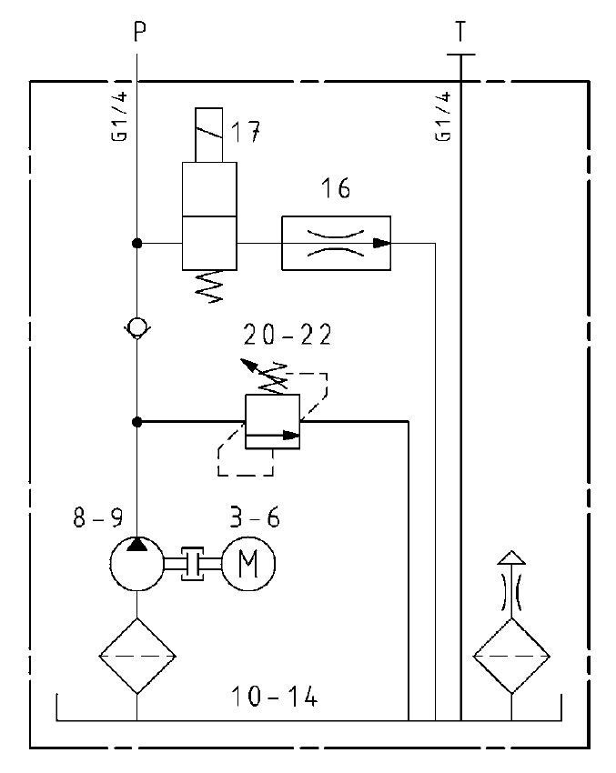
The tank, pump size, motor type, pressure setting, directional valve and flow control valve are configurable items.
Details
The KH-power pack KHW055U08K015VFYB1A155 has got a 0,55 kW AC/50Hz motor (1450 U/min), 0,8 ccm/U displacement volume, 1,2 l/min flow and 250 bar max. pressure. It has an 1,5 liter plastic tank in vertical mounting position, mounting foot, without flow control valve, 2//2-way poppet valve (NC) with 24 VDC selenoid. Motor mounting position is position 1, tank mounting position is position A. The seeting of the relief valve is 155 bar.
Configuration key
Subsequently the configuration key of the KH-power pack series is shown.

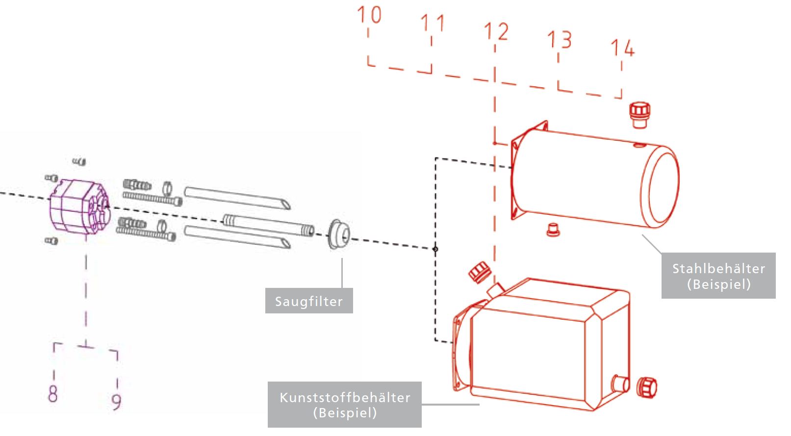
Each configuration digit determines individual attributes. Following all options are shown in an explosion drawing.
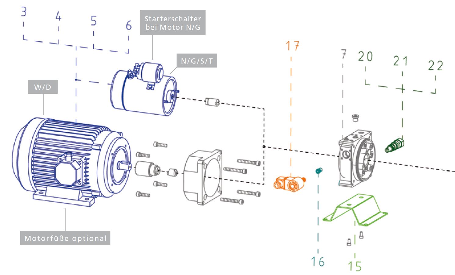
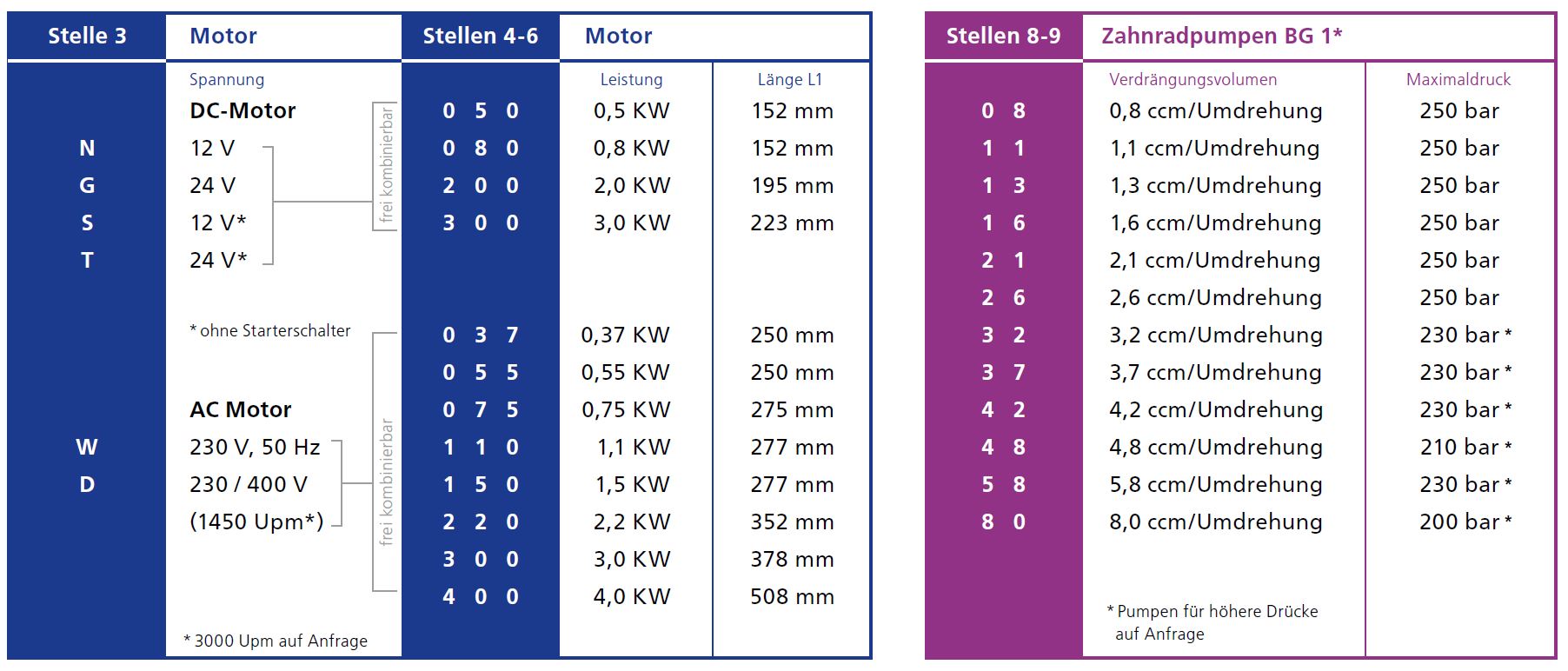
Digit 3 determines the supply voltage. Digit 4-6 configures the motor power and the motor length L1. Digit 8 and 9 define the displacement volume of the gear pump. Related to the pump size is the max. pressure.
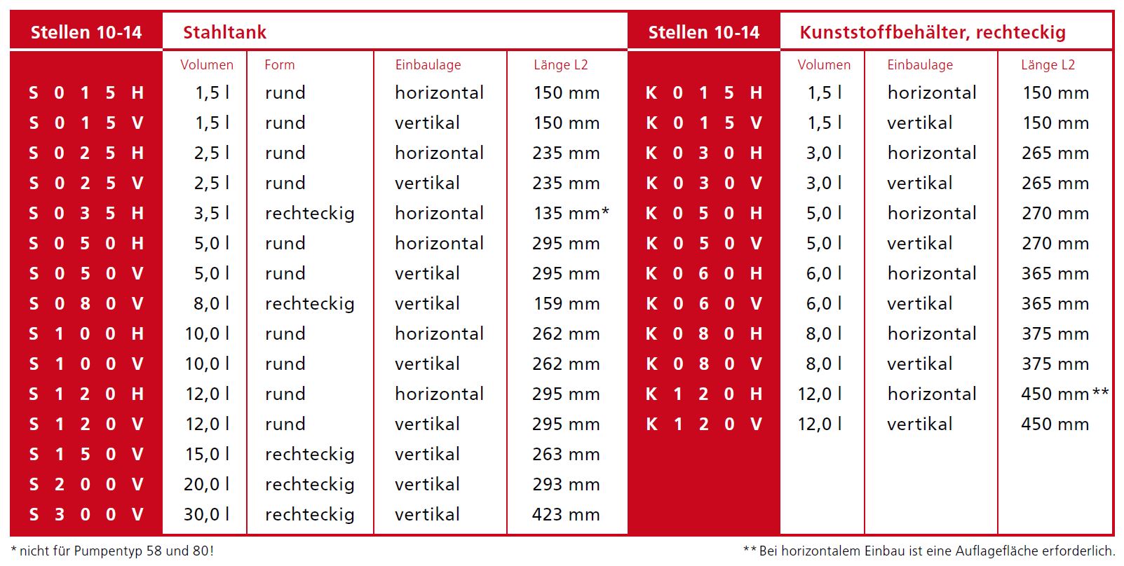
The digit 10-14 defines the tank type, the size of the reservoir as well as its shape, material, mounting position and length L2.
The shape and composition of the tank is shown in the following explosion drawing.
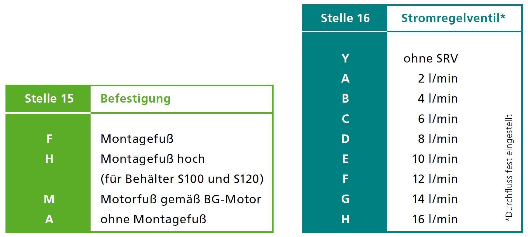
Digit 15 determines the mounting type and digit 16 the flow rate of the lowering flow control valve.
Digit 17 defines the attributes of the optional poppet type directional valve, e.g. manual operation, supply voltage (12VDC/24VDC/230VAC).
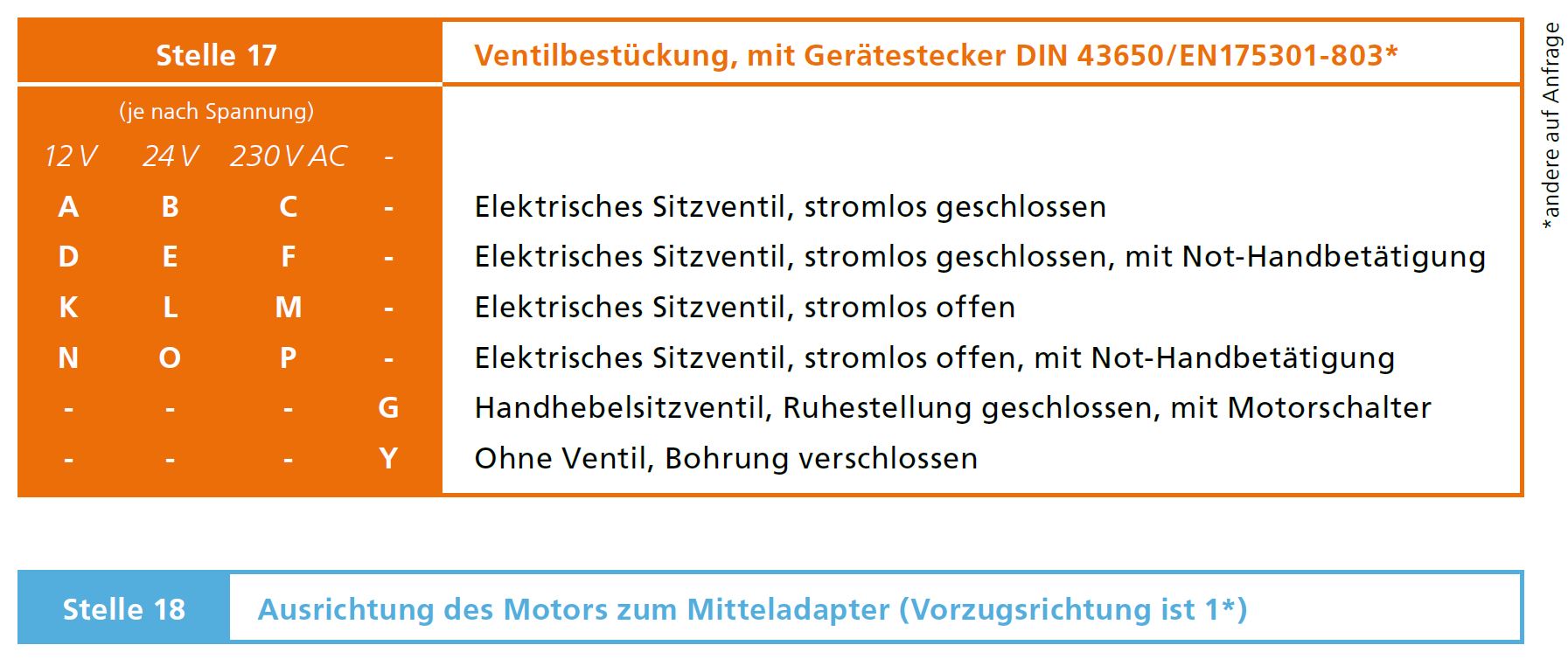
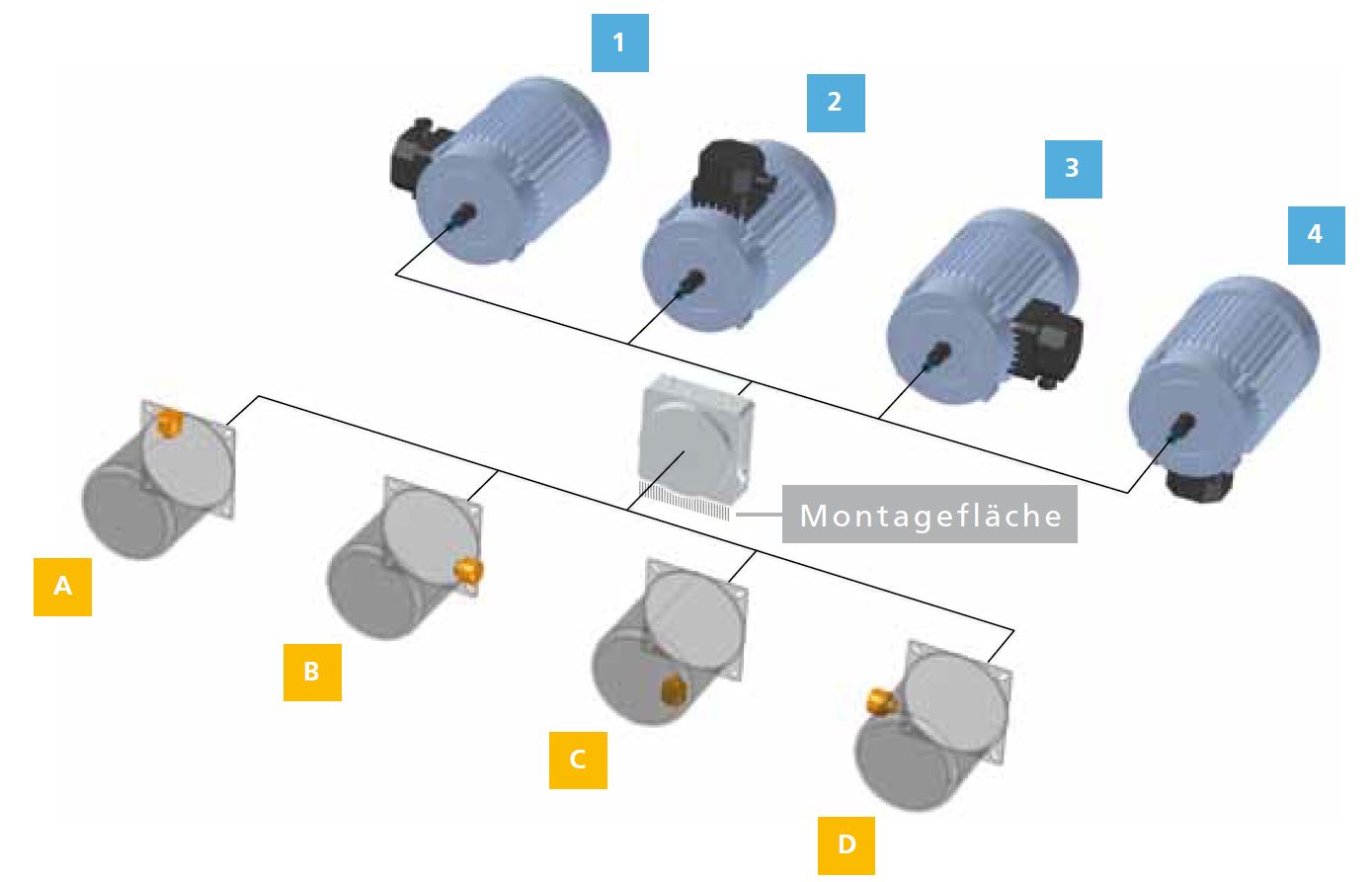
Digit 18 describes the orientation of the motor in relation to the center manifold, digit 19 the mounting position of the tank and breather. Available options are shown below.

Digit 20-22 encode the pressure setting of the main relief valve.
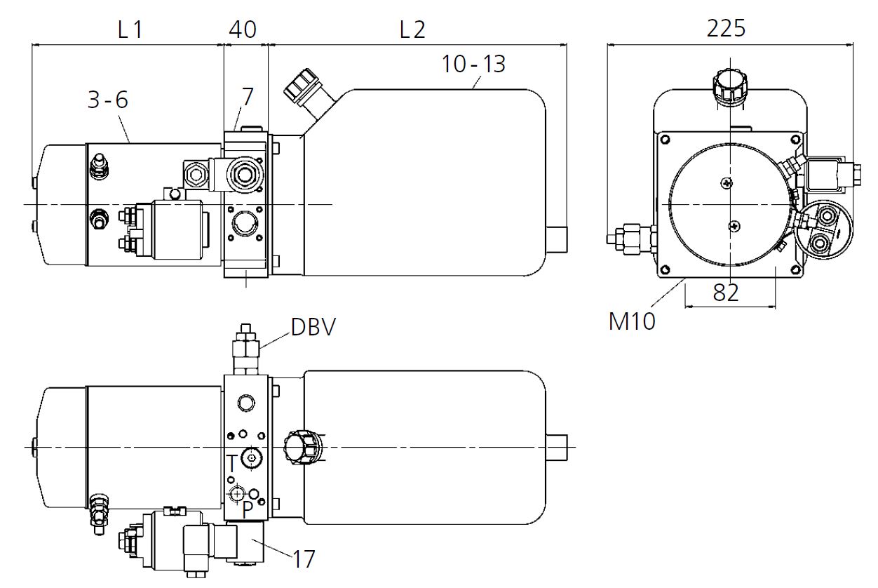
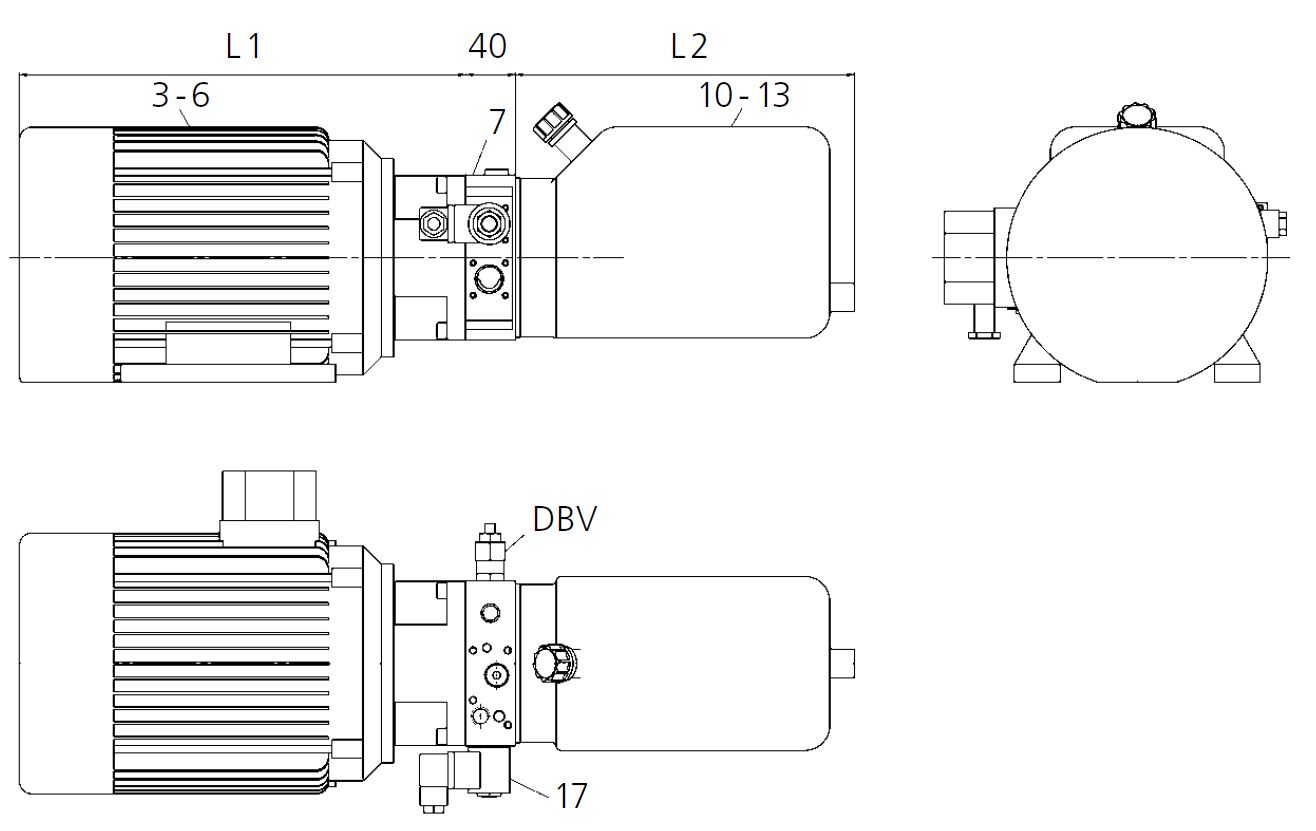
Dimensions
Subseqently the dimensions of the power pack are shown, for the plastic type tank configuration as well regate mit Kunststofftanks und Metalltanks, sowie Gleichstrommotoren und Wechselstrom/Drehstrommotoren gezeigt.
FLUITRONICS is a specialist in the development and manufacture of customer-specific series solutions in the field of drive technology and control. If you cannot find any suitable products in our database, please contact us or visit our homepage (www.fluitronics.com). We would be happy to show you what the path to your individual solution can look like.